
Article 2.2. STL file explanation and fixing
Introduction
In our last article we explained how to generate your CAD (Computer-aided design) model in order to get started with 3d printing. For those wanting to design the 3D object themselves, we offered a review of free and paid online software. For the users that prefer to download object files from other designers, we offered a selection of websites with 3D models database. The next step of making a 3D printing design is to understand STL files and how to create a good one. Are you struggling with faulty STL files? Most of them aren’t immediately ready for printing. Models seemingly perfect on screen may be filled with defects which make 3D printing difficult, if not impossible. Go ahead and read this article explaining how to easily fix your CAD files and how to prepare them for the slicing software!
Wait a minute! What is an STL file?
The STL file (StereoLithography File) is the standard language of the prototyping world, the file format that all geometry creation tools write, and that all prototyping systems read. In a 3D print file, the object is constructed out of a set of triangles, also known as mesh. These triangles surround the volume of the object. The denser the mesh (i.e. the higher the amount of triangles) the more detailed the surface of your printable objects will be. The build time is 100% related to the volume and the build height of the object, it is not related to the density of the mesh. The details have no effect whatsoever on the build time. The more detailed the mesh, the bigger the file becomes, because there are more meshes and therefore more coordinates inside the file. This is of course harder to process for most slicer software. In Tripodmaker we are proposing Prisma, a cloudbased slicer platform perfectly fitted for your Tripodmaker professional 3D printer. It is easy to use and results in perfect prints. Prisma is more powerful than a regular computer software and therefore handles even the most complicated job easily. Click here to find out more about Prisma: http://www.tripodmaker.com/page/prisma
An STL file can be created with most of the CAD programs or with a scanner and contains the data of the triangles. If triangles (i.e. surface data) are missing or overlapping in the STL file, you might not be able to print your 3D object. In that case the STL model needs to be fixed, by plugging the hole or addressing the overlap, before continuing. You can fix the STL file with a free application like Netfabb Basic. When you make a prototype it will be an exact copy of your STL file. If there are errors in your file, you may not be able to get a prototype made. This is why we consider it is a good investment to take some time and understand STL files and how to create a good one. In this post we are going to go through a simple example, showing how to use this great free tool, to automatically repair STL files for 3D printing. It is quite fast and you just need to be able to find your way around the user interface!
TUTORIAL: Repair STL files in NETFABB BASIC
Here is a detailed and clear tutorial by Thomas Sanladerer, showing how to prepare and fix STL files that would otherwise cause problems during 3D printing. All big CAD software like Solidworks or Inventor, but also Sketchup, OpenSCAD and Blender can export STL files. Like we said, the STL file defines the surfaces of your part. The more complex your parts are, the more can go wrong when your program tries to decide how to arrange those triangles, to make them as similar as possible to the original part. Modern slicers can automatically work around some of these errors but we highly recommend that you do these repairs by yourself since these can often introduce artifacts that will only show up once the part is printed. Another common problem with printable files is that they are often not oriented properly, so unless you want to make heavy use of support material, you should check that the part you are going to print has a large, flat surface that can stick to the build platform and is oriented in the right direction.
For this job, we are going to be using Netfabb Studio basic, which is a popular free tool for 3D printing. In fact, the professional version also includes a slicer. The process we will follow will basically be as follows.
- Load your file and check Netfabb’s preliminary analysis
- Perform Repairs
- Apply repairs to your file
- Export the repaired file as a new STL
- Load your STL file and check Netfabb’s preliminary analysis
So let’s get started. If you haven’t installed it yet, Netfabb basic for Windows, Linux and Mac is available for free at http://www.netfabb.com/downloadcenter. After installing, you will need to register it using your email address. To open up a file, choose ‘Open’ under the ‘Project” menu in Netfabb. It will look like this.
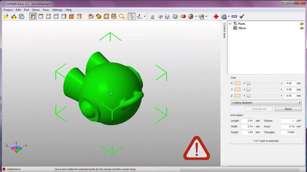
When opening an STL file, Netfabb performs a preliminary analysis to determine if there are issues that could cause problems during 3D printing. The most common issues include holes and triangles with invalid orientations. You can rotate the view while holding the right mouse button and zoom in and out with the mouse wheel. In the bottom right corner, Netfabb will show you the dimensions of the part you just opened. This is important to check if you are using the parts that were imported from CAD programs. STL files only store dimensionless units for the sizes, so RepRap tools generally assume those units to be millimeters. However, some programs use inches or centimeters when exporting, which will result in parts that appear way too small. To fix that, we can use the “scale” tool, which is up here.
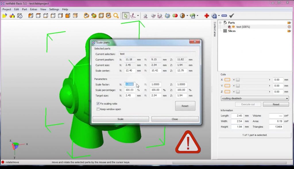
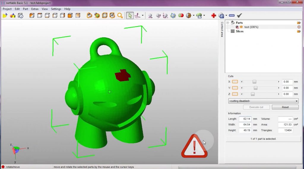
Use a scaling factor of 25, 4 if your part was exported in inches, or 10 for centimeters, then hit “scale” and double-check that the reported dimensions are correct. Now, you might have noticed the little warning icon at the bottom of your screen, which indicates that your part still has errors in the data. If you do not see the red attention warning, congratulations, your file is very likely ready for 3D printing and nothing further is needed.
- Perform repairs
If problems are found, you will often see the errors as red spots on your part. The best way to deal with these is by using the “Automated Repair”, which usually manages to get almost every file into a printable shape. To start, click the red cross on your toolbar and select “Automated Repair”, then choose the “Default Repair” and hit “Execute”.
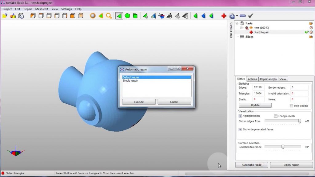
At this point you’ll notice that another ‘layer’ is created underneath the ‘Part Analysis’. The triangular mesh is now shown on the model and new options and information are available in the lower pane. Press ‘Update’ to see a list of different errors. Now, select ‘Automated Repair’ and then choose ‘Default’.
Netfabb will now process a series of repair algorithms in order to make the STL file printable. You can follow up these steps by clicking on the Repair Scripts tab in the lower right of the information pane. This will probably take some time. The more detailed the mesh, the longer it will take. A status bar in the lower right corner will show progress.
When the repair process is complete you can again press the ‘Update’ button under the status tab. You should see zero border edges, invalid orientations and holes. If your part is a single object it will likely indicate the preferred shell. Not optimum multiple shells will not usually cause printing problems. You should also visually verify that your model still looks the same as the original one. In some cases, Netfabb automated repairs may create solids where in fact a hole was intended. This is rare but you should still check visually.
At this point, the file will usually print just fine. If the “Automated Repair” didn’t pick off all errors, you might want to try to “Remove Degenerate Faces” option in the actions tab. Choose a tolerance of about 0, 01 and hit ok. This will completely remodel your file and give you another chance that the “Automated Repair” picks off all errors, so run than again.
- Apply repairs to your file
We’re not done yet as we still need to apply the repairs to the originally loaded file by pressing ‘Apply Repairs’ in the lower right corner. This removes the analysis and repair layers and fixes the original rendering. You should normally see the original green rendering without the red attention warning. You should also see a volume calculation. Now hit “Apply Repair” then “Remove Old Part”. The last step is orienting the part, which is very simple in Netfabb. Use the “Align to Bottom Plane” tool and double-click the side of your part that you want to stick to the build platform.
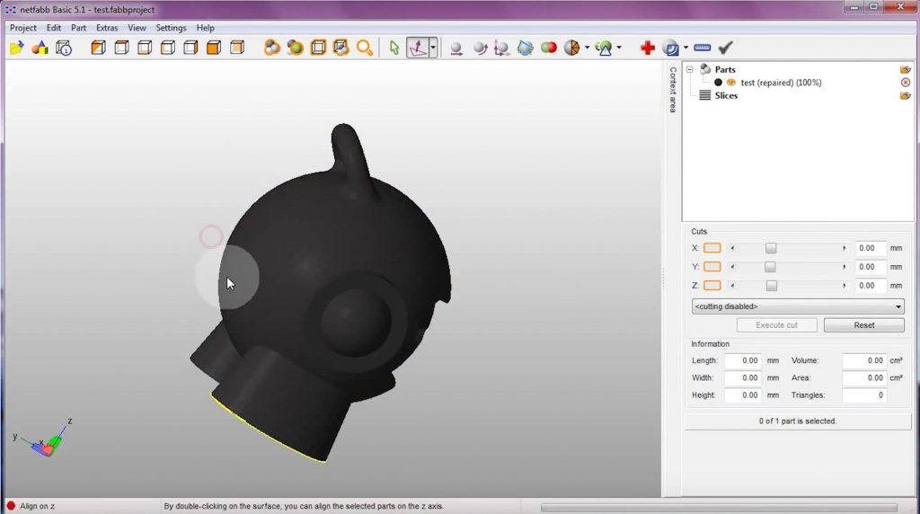
- Export the repaired file as a new STL
Since we started this process to create a clean STL file we now need to create a new, repaired file. Make sure the part is selected and green, then click “Part”, “Export Part”, “STL” and choose where you want to save the STL. Netfabb will automatically create a filename composed of the original with ‘repaired’ appended so you don’t have to worry about overwriting your original file. If successful, instead of a large red ‘x’ you will see a green check mark. So that’s the whole process of preparing a file for the slicer! You should now run through this process for every part you print. We promise that once you have figured it out, it’s super-fast to do as well. Congratulations, you now have a printable STL file!
Source: https://www.youtube.com/watch?v=StqAtQIR3Bs
Conclusion
Once you have managed to create or repair your STL file, you need to feed it into the slicing software. The slicing software (also called a slicer) converts the STL file into a machine code, the ‘g-code’, which is basically the path per layer that the 3D printer must follow in order to construct the printed object. Stay tuned for our next article and find out more about the slicing software. We will provide a detailed selection of all software required to prepare and execute a 3D print. We hope that you have found this article useful! For you, impatient reader, download our free e-book here!